Posted on

grbl, Windows XP and Boarduino

A quick note / tutorial to help anyone trying to find out the same information that I was!


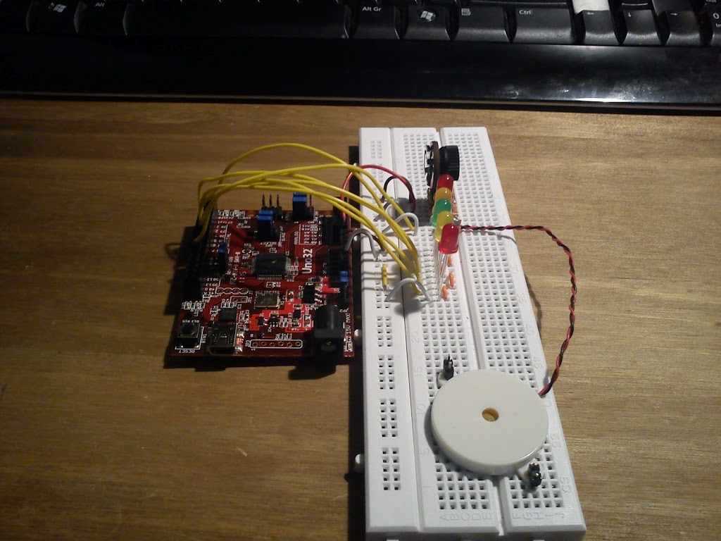
I am looking to set up a CNC system and have chosen to go down the grbl route and use a boarduino. The first hurdle of getting grbl on to the boarduino using the hardware I have on my desk. A lot of sites made this sound a lot harder than it was in the talking about AVR programmers and all sorts


EDIT: The hex file supplied below has an error – the motor drive pin doesn’t work. I have created a new HEX file which I will upload when I have tested it.


I have provided a summary after the jump:


OS – Windows XP, this would probably have been a lot easier with linux!


grbl – I used the hex file from here – https://github.com/downloads/synthetos/grblShield/grbl-latest.hex


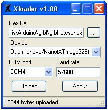
Upload to boarduino – xloader available from – http://russemotto.com/xloader/ (ArduinoUploader didn’t work for me)


Communicate with the board – G-Code sender – https://github.com/OttoHermansson/GcodeSender/downloads


I am assuming that you have your boarduino assembled, tested and are set up to send stuff to it via a usb to serial cable or similair, I use the Arduino USB2Serial Light board (more info on the boarduino – http://www.oomlout.co.uk/index.php?main_page=product_info&products_id=234 or http://www.adafruit.com/products/72).


1) Download everything and unzip the files.


2) Open  Xloader


3) Select your hex file


4) Set device to Duemilanove/Nano(ATmega328)


5) Set appropriate COM port


6) Hit upload


7) Open G-Code sender


8) Under serial select appropriate COM port


9) Press open


10) Under command type $ and hit return


11) you should get something similair to the following:


To change a setting, for example to set steps/mm x to 200, type $0=200.


Please be aware that this is untested other than serial communication – I have no idea yet if there are any problems further down the line.


Hopefully this will save someone else from having to trawl the internet for hours with many failed attempts!


Now all I have to do is build some sort of CNC machine to attach it to…

Posted on

Robot Gripper

I have designed a robot gripper for a Turnigy mini TG9e servo. A paypal link for the laser cut acrylic components is at the bottom of the page. The gripper is laser cut from 3mm and 5mm acrylic and bolted together with M4 16mm machine screws.


The servo arm is used to drive the gripper.


The green acrylic under the servo is the 5mm section. Make the bolts finger tight and adding a blob of superglue to the nuts helps keep everything solid.

The servo hooked up to a boarduino.


I am selling the acrylic parts for £5 (plus shipping) via paypal.


You will also need a small servo such as the Turnigy TG9e (I believe the TG9 will fit as well), 7x M4 16mm machine screws, 7x M4 nuts,14x M4 washers and a teeny tiny screw to attach the servo arm to the gripper (the ones with the servo are ideal)


The “wrist” has 2x 4mm holes but if you require something different just let me know when ordering.


Servos can be sourced here .
M4 hardware is available from all good hardware stores 😉
Instructions can be downloaded here.

Posted on

Bluetooth Headset

Simple mod from last Saturday night (I really need to get out more!).

I have a pair of bluetooth headphones but unfortunately the headband is broken and one of the speakers is a bit dodgy so I decided to mod it to have a 3.5mm socket.


More after the break.


When I got them open I found that the battery was in the left ear and the main-board in the right. After tracing the cables it was a simple job to move the battery to the main unit. You may notice the mic on the right of the pic below, basically I forgot about it as I do not need it – oops.


Pretty much everything on the board is surface mount but luckily the headphone wires and through hole. Even so the holes were tiny and plated so removing the old solder was a nightmare, in the end heating up the wire and pushing it through. I the soldered on a set of wires for connecting to the socket scavenged from an old soundcard.


Not the most delicate job I have ever done but never mind! I then ran everything through a breadboard to get the wiring right and test everything.


After soldering on the socket I then knocked up a quick case laser cut from 3mm acrylic.


The buttons were nice and simple as they were surface mount push buttons so I just cut some button shape hole and stuck the middles of the cut outs back in on top of the buttons.


Although not the most refined design ever it works pretty well and opens the device up to a lot more applications than previously. I may re-design the case at some point as it doesn’t fit perfectly but for now it will do!

We are still waiting for the test tubes to arrive for the Axolotl sensor after finding some of the right size and will put a full post up when its complete.

The problem with the interference and the laser temp sensor has proved impossible to re create anywhere else! We will work on that one.
Posted on

Fire Detector 2

So I set up the Chipkit Uno32 with the temperature sensor TMP36 from oomlout.com, installed the serial port monitor on the laser pc and tested the system. All fine so far.


The data collected was pretty good as well.


The left shows room temp with the slight increase being the heat detected from my hand on the outside of case. The peak is where I took a very technical approach and waved a lighter under the sensor!


Unfortunately as soon as I turned the laser on it all went wrong! The data became massively noisy as you can see here:


The flat bit in the middle is where I turned the laser off. 

The laser is not running, just sitting in ‘standby’. The only thing running is its controller and the steppers in a fixed position.

First thing I did was swap the USB port to a different PC, just in case, but no improvement. I also ensured that the Uno32 was not shorting on the body of the laser.

Next I turned off the laser but left all the cooling and extraction on, this gave good data!

So in summary, the laser is interfering with Uno32 / temp sensor despite them being isolated from each other. Great. I will try increased insulation and moving the Uno32 off the machine somewhere.

If anyone has any suggestions (or something really obvious I have missed) please let me know!

Posted on

Fire Detector

After Martins fire, and have a near miss myself I am planning to build a fire detection system for my laser. I am already building an Axolotl temperature sensor system (which I am logging at the moment) so when that is complete I will have a look at using a similar system for fire detection. Whilst the temp sensor is being finished I am going to log the temperature in the laser to see what sort of range I am dealing with. For this I am going to use the chipkit / arduino prototype for the Axolotl system and write something simple to monitor the com port on the PC.

I will strip the LED and buzzer off and hook up the temp sensor directly.

More details and code will be published when I have it hooked up.