Posted on

DHT Sensor for Gary

Gary the gecko gets a bit funny about his environment so we have to keep an eye on his temperature and humidity. We could have gone a purchased one but that would have been too easy! One ATMega328, home brewed PCB, LCD screen, DHT11 sensor and a laser cut case and we are away!
Not many notes on this one as the PCB creation was experimental and I will be writing it up fully later.
Anyway, here are some pictures.
More pics:

The button is so it doesn’t burn power with the backlight
Like this
Sensor in an old mic housing.
Gary
Gary
Code if you want it, un-tidied and barely changed from Adafruits code. You will want the library on the tutorial as well.
**************************************************
 // Example testing sketch for various DHT humidity/temperature sensors

// Written by ladyada, public domain

#include “DHT.h”
#define DHTPIN 13     // what pin we’re connected to
#include <LiquidCrystal.h>
LiquidCrystal lcd(5,6,7,8,9,10);
#define DHTTYPE DHT11   // DHT 11
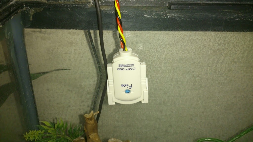
// Connect pin 1 (on the left) of the sensor to +5V
// Connect pin 2 of the sensor to whatever your DHTPIN is
// Connect pin 4 (on the right) of the sensor to GROUND
// Connect a 10K resistor from pin 2 (data) to pin 1 (power) of the sensor

DHT dht(DHTPIN, DHTTYPE);

void setup() {
  lcd.begin(16, 2);
  lcd.clear();
  Serial.begin(9600);
  Serial.println(“DHTxx test!”);
  lcd.print(“Starting…”);
  dht.begin();
  delay(500);
}

void loop() {
  // Reading temperature or humidity takes about 250 milliseconds!
  // Sensor readings may also be up to 2 seconds ‘old’ (its a very slow sensor)
  int h = dht.readHumidity();
  int t = dht.readTemperature();

  // check if returns are valid, if they are NaN (not a number) then something went wrong!
  if (isnan(t) || isnan(h)) {
    Serial.println(“Failed to read from DHT”);
  }
  else {
    Serial.print(“Humidity: “);
    Serial.print(h);
    Serial.print(” %t”);
    Serial.print(“Temperature: “);
    Serial.print(t);
    Serial.println(” *C”);
  }

  //LCD Display
  lcd.clear();
  lcd.setCursor(0, 0);
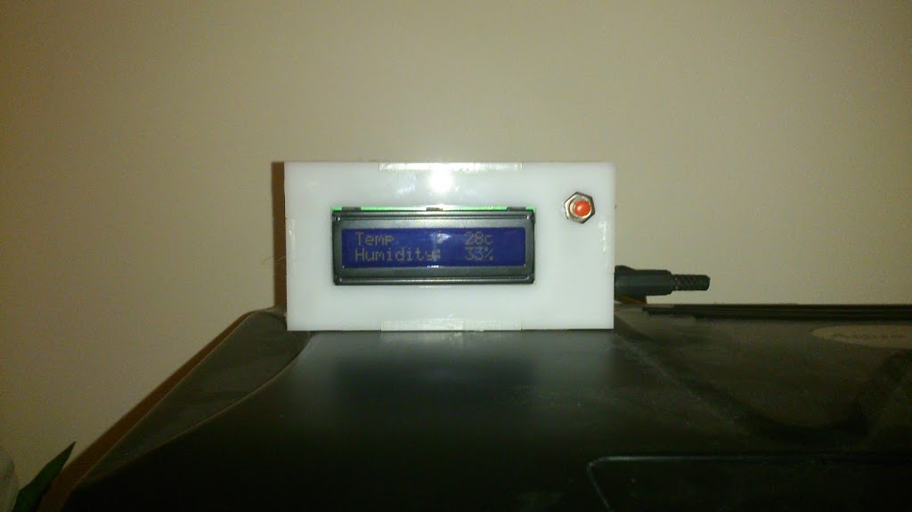
  lcd.print(“Temp    : “);
  lcd.setCursor(11, 0);
  lcd.print(t);
  lcd.setCursor(13, 0);
  lcd.print(“c”);
  lcd.setCursor(0, 1);
  lcd.print(“Humidity: “);
  lcd.setCursor(11, 1);
  lcd.print(h);
  lcd.setCursor(13, 1);
  lcd.print(“%”);
  delay(1000);
}

*****************************************
Posted on

Ebay Listing

We have finally got round to starting to add some products to ebay, all laser cut of course. Ebay shop. So far we have quite a few home decor items which are great but the most interesting item is a Breadboard Component Holder.

More after the break


After getting fed up of bent pins on our breadboard compatible components (being of the “stick it in the box/drawer” school of tidy) we decided to come up with something that we could use to store these items. We now have a few of these on walls and desks and in one case on the side of a PC!

With a couple of male headers we can use them to store dev boards like the Stellaris Launchpad, Chipkit and of course Arduino!


We even use them to store ICs like this L293D Motor Driver


Only problem we have is that it takes quite a while to laser drill the six thousand two hundred and nine holes!


You can get one here – Breadboard Component Holder

Posted on

Halloween Monster Box

We normally throw a Halloween party in our house but this year we have managed to dodge the bullet friends of ours have volunteered to have a house full of over sugared children.

I couldn’t leave it at that however so I have created a Monster Box for my sons to take with them and scare the other guests.


The parts list is pretty basic:


Arduino Uno – http://www.hobbytronics.co.uk/arduino/arduino-uno-r3


Distance Sensor – http://www.hobbytronics.co.uk/GP2Y0A21-distance-sensor?keyword=distance


6 AA Battery Pack – http://www.maplin.co.uk/aa-size-battery-holders-31427


Mini 9g Servo – like these but there are loads on ebay. None that I can recommend having never used them http://www.ebay.co.uk/itm/5x-Tower-Pro-Micro-RC-SG90-9G-Servo-for-Car-Plane-Boat-Helicopter-Hobby-UK-/290787324013?pt=UK_ToysGames_RadioControlled_JN&hash=item43b446706d


Bits of wire, string, sticky tape, sticks, paint, glue etc.


The principle is pretty simple:

Distance sensor feeds back distance to Arduino
Arduino triggers servo when distance is less than n cm
Box stays shut for x time then opens again (as long as distance n is great enough)

Servo signal wire is connected to pin 9, Distance sensor on pin A0, ground to ground, +ve to arduino 5v. Battery pack is to the arduino gnd and Vin rather than the barrel jack.


The sensor has a slot cut in the front of the box and is taped in place (Bottom of the Picture).


The servo has a stick (part of a very broken RC helicopter frame in this case) wired to the end of the arm, the stick is then stuck to the lid of the box.


The servo itself is stuck on to the side of the box with, surprise surprise, more sticky tape.

I have run out of switches so I soldered up a bit of protoboard with a couple of header pins and used a couple of jumpers as the switch.


The code is pretty simple and I am sure I will be told, at length, the number of ways that it could be done better!

****************************************************

int sensorPin = A0;
int distance = 0;
int servopin = 9;
int time = 0;
#include <Servo.h> 
Servo myservo;
void setup() 
  myservo.attach(servopin);
  Serial.begin(9600);
void loop(){
distance = 12343.85 * pow(analogRead(sensorPin),-1.15);
Serial.println(distance);
if (distance<75){
myservo.write(180);
delay(3000);
myservo.write(10);
time = random(1000, 5000);
delay(time);
}
else{
myservo.write(10);}
delay(100);
}

****************************************************

Pre decoration the box runs like this


Finally finished – not perfect by a long shot but it should entertain a group of 2-4 year olds for 10 minutes!


I apologise for the video – it wouldn’t focus on the black when it was closed! (this is the best of the bunch though!)


Posted on

Boarduino ATTiny Programmer

We have been doing a lot of ATTiny programming recently and decided to simplify the process by making a board to plug everything in to rather than breadboarding it every time.


Rather than perf board we decided to make up a Laser masked PCB board  to take a boarduino, ATTiny and reset overide capacitor. More after the break:


A comprehensive overview of the setup can be found here http://hlt.media.mit.edu/?p=1695.


We did have a couple of problems getting everything to compile and had to manually install winavr, modify our ATTiny libraries and modify softwareserial. Most of this is due to using windows and upgrading from arduino versions 0023 to 1.0 half way through a project! oops.


The new setup is much more a plug and play solution rather than trying to set up a breadboard each time and we minimised the copper removed from the board which will save our etchant and looks nicer on the board!


Below is the board graphic as a bitmap for running through the laser. This is different to the board above in that it actually works, unlike version 1!

EDIT: I have discovered that Arduino 1.0 will not programme the ArduinoISP sketch correctly onto the boarduino. I have to load this using Arduino 0022 or 0023. I can then use 1.0 to programme the AtTiny – Chris.

Posted on

grbl, Windows XP and Boarduino

A quick note / tutorial to help anyone trying to find out the same information that I was!


I am looking to set up a CNC system and have chosen to go down the grbl route and use a boarduino. The first hurdle of getting grbl on to the boarduino using the hardware I have on my desk. A lot of sites made this sound a lot harder than it was in the talking about AVR programmers and all sorts


EDIT: The hex file supplied below has an error – the motor drive pin doesn’t work. I have created a new HEX file which I will upload when I have tested it.


I have provided a summary after the jump:


OS – Windows XP, this would probably have been a lot easier with linux!


grbl – I used the hex file from here – https://github.com/downloads/synthetos/grblShield/grbl-latest.hex


Upload to boarduino – xloader available from – http://russemotto.com/xloader/ (ArduinoUploader didn’t work for me)


Communicate with the board – G-Code sender – https://github.com/OttoHermansson/GcodeSender/downloads


I am assuming that you have your boarduino assembled, tested and are set up to send stuff to it via a usb to serial cable or similair, I use the Arduino USB2Serial Light board (more info on the boarduino – http://www.oomlout.co.uk/index.php?main_page=product_info&products_id=234 or http://www.adafruit.com/products/72).


1) Download everything and unzip the files.


2) Open  Xloader


3) Select your hex file


4) Set device to Duemilanove/Nano(ATmega328)


5) Set appropriate COM port


6) Hit upload


7) Open G-Code sender


8) Under serial select appropriate COM port


9) Press open


10) Under command type $ and hit return


11) you should get something similair to the following:


To change a setting, for example to set steps/mm x to 200, type $0=200.


Please be aware that this is untested other than serial communication – I have no idea yet if there are any problems further down the line.


Hopefully this will save someone else from having to trawl the internet for hours with many failed attempts!


Now all I have to do is build some sort of CNC machine to attach it to…