Posted on

USB Microscope

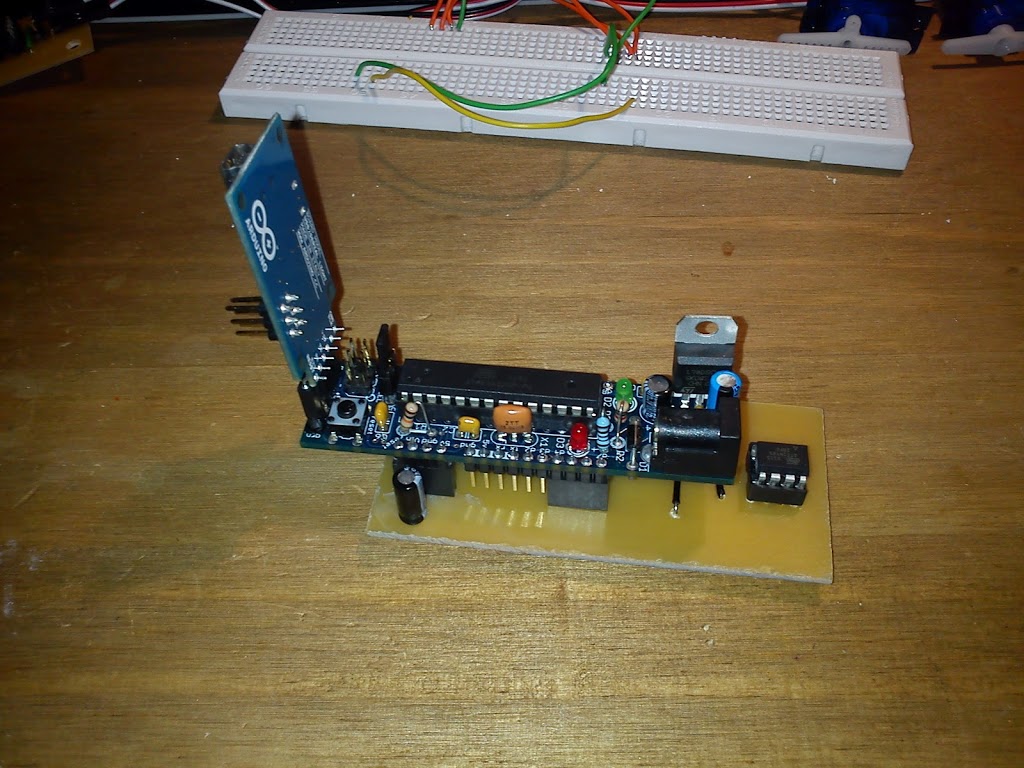
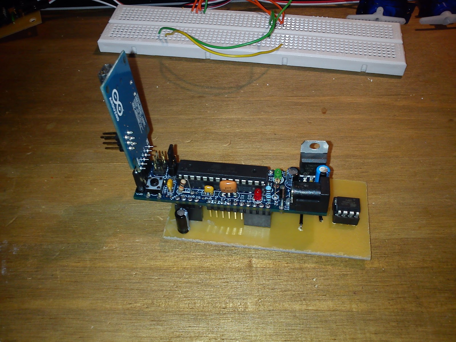
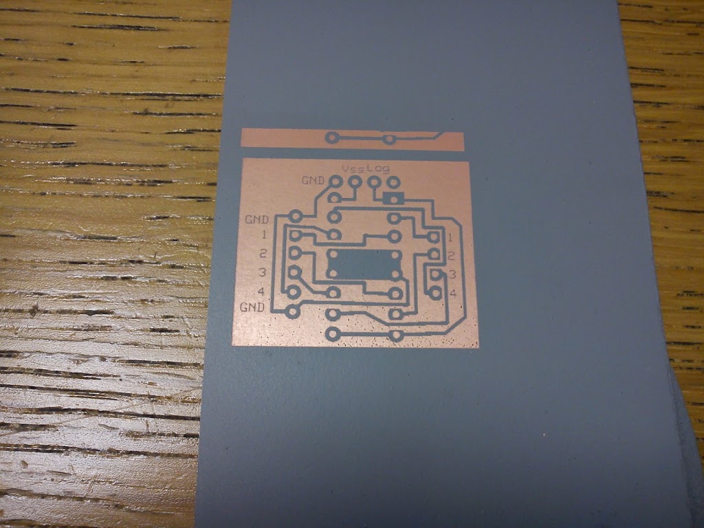
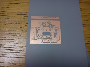
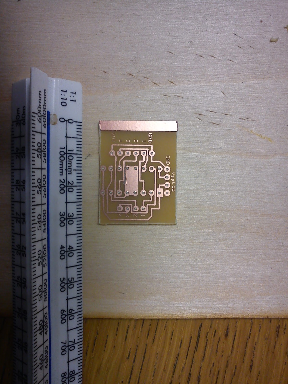
We were lucky enough to be given a USB microscope this christmas so decided to try it out by soldering some Atmega8A in a TQFP32 package that we got REALLY cheap from China. We etched a breakout board using the vinyl on paper – laser print – heat transfer technique (we will write a post up about that later) and prepared to solder.

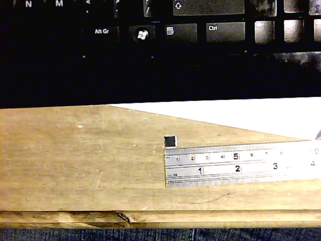
We realised they were small but hadn’t realised HOW small!


More after the break


Luckily we could get far closer than we will ever need to solder.


 The microscope can also record video – below is our first attempt at soldering this size package. So far everything seems to have been successful!


Not the most thrilling video in the world but it works!


Posted on

Boarduino ATTiny Programmer

We have been doing a lot of ATTiny programming recently and decided to simplify the process by making a board to plug everything in to rather than breadboarding it every time.


Rather than perf board we decided to make up a Laser masked PCB board  to take a boarduino, ATTiny and reset overide capacitor. More after the break:


A comprehensive overview of the setup can be found here http://hlt.media.mit.edu/?p=1695.


We did have a couple of problems getting everything to compile and had to manually install winavr, modify our ATTiny libraries and modify softwareserial. Most of this is due to using windows and upgrading from arduino versions 0023 to 1.0 half way through a project! oops.


The new setup is much more a plug and play solution rather than trying to set up a breadboard each time and we minimised the copper removed from the board which will save our etchant and looks nicer on the board!


Below is the board graphic as a bitmap for running through the laser. This is different to the board above in that it actually works, unlike version 1!

EDIT: I have discovered that Arduino 1.0 will not programme the ArduinoISP sketch correctly onto the boarduino. I have to load this using Arduino 0022 or 0023. I can then use 1.0 to programme the AtTiny – Chris.

Posted on

Laser Engraved PCB

I thought we were being really clever with this one but apparently it has been done before!

We needed a PCB making for a simple stepper motor driver and thought “why can’t we use the laser?”. A quick trip to maplins we had a copper clad board and some grey automotive primer.

The process itself is really simple:


1) Spray board with Primer


2) Engrave board with design


3) Etch Board


4) Remove remaining primer with acetone


5) Solder Board!


You will have to excuse the soldering – My drill bit was too large and i didn’t have any flux!


We are not going to be making proffesional boards like this but for a clean, high speed way to make a PCB its pretty good.