Posted on

Introduction

The XLC is a company set up by myself to primarily supply laser cutting to the print industry, but it wasn’t long before we had started to branch out in to other materials and services!

One of the things we started to produce quite early on was wargame terrain for myself and some friends. After a while I got organised and started to prepare actual kits and sell them via ebay. As time went on I designed more and more pieces until it was decided that we should actually do something with these designs and The XLC Wargame Terrain came in to being.

Over the coming months we have plans to release new pieces, launch a Kickstarter for a particularly large item and generally focus on making models and terrain, because after all, its a lot more fun than real work!

To get you interested here are a few pieces we have built recently:

Posted on

Fun with 3D printing – Printing Surface

Just a brief one to update everyone on what we have been up to. Basically we have been heavily focused on the printing side of the business recently so haven’t had time for any fun projects. We did, however, get to go to a seminar on 3D printing and the The National Museum of Computing (FYI well worth a visit, especially if you get to have a guided tour). The equipment on display was excellent and is on our wish list (thank you Triformica for the invite) but is a LITTLE out of our budget just at the moment. But… it did get us thinking about how useful 3D printing would be in house, just for prototyping and component repair so after having a look around we decided to buy a Printrbot Simple kit to cut out teeth on. We now have 3D printing capabilities! No, we cannot produce commercial grade pieces but it is a lot of fun.


I would warn anyone planning to purchase one of these who isn’t in to tinkering that at this price range you WILL need to fettle and tweak it to get even basic prints out. That’s not a failing of the machine as such but this is emerging technology and is not very refined.

We have had the machine 3 weeks and have already made a few changes which I will go in to detail later.

As a quick summary we have so far:

Home etched a heated bed.
Re-Designed the bed to take a heated bed and glass surface.
Made a new power supply from a PC ATX supply.
Built a spool holder 2 spool holders a spool platter.

The first thing I will discuss however is the printing surface for PLA filament. If you don’t already know getting the filament to stick to the bed on the first layer is a right pain in the backside. We tried acrylic (too stuck down, bed was scrap), ply (sometimes worked), hairspray on glass (worked 50% of the time), masking film (worked 50% of the time), plain paper (worked too well) and pretty much anything else we could stick in there. In summary the prints were lifting, lumping or generally being a pain most of the time.

Our Solution:

Glass bed heated to an indicated 55°C, layer of masking film (Perfect Tear Main Tape) and a solution of 50% water, 50% PVA glue on top of the tape. So far we have not had any problems with this at all. We can run the head a little higher, splurge (technical term) the filament a little less, run faster, and remove the part by lifting the tape off the bed. We have to re-coat each time but it takes moments (our working area is only 95x100x100mm) and costs practically nothing (we even have the tape in 100mm width by the box load). The only issue we have is a little tape gets glued to the bottom of the piece but we can easily remove this with water. When putting on the PVA the tape wrinkles a little but soon flattens out when it drys.

Hopefully someone will find this useful and not have the headaches we have!

Other mods to follow soon 🙂

Posted on

Round Peg, Square Hole

Today I had to purchase a cheap tap and die (this one) set to repair a heat press. It worked perfectly well on steel so I thought I would try acrylic.


After tapping a few holes for no reason whatsoever I thought I would try threading a slot as a replacement for a capture nut. 


As it turns out it is practically impossible to do and keep the tap anywhere near central!

20 minutes later I knocked up a jig (with tapped holes of course) to hold everything in alignment. You can download the plans here.


Its similar to a doweling jog but a lot less complicated. Surprisingly it works like a charm! The tap cuts easily (although if you go too deep and reach the end of the slot the whole thing binds up completely and will not undo) and the final joint is surprisingly strong. Probably not as strong as the captured nut but it does the job.


Specs if anyone wants to try this:
Acrylic – Cast 5mm Clear (Perspex) 
Tap – M4 x 0.7
Hole for thread – 3mm
(3.2 is quoted for M4 but with laser kerf 3mm seems better)
Slot – 3mm


Posted on

DHT Sensor for Gary

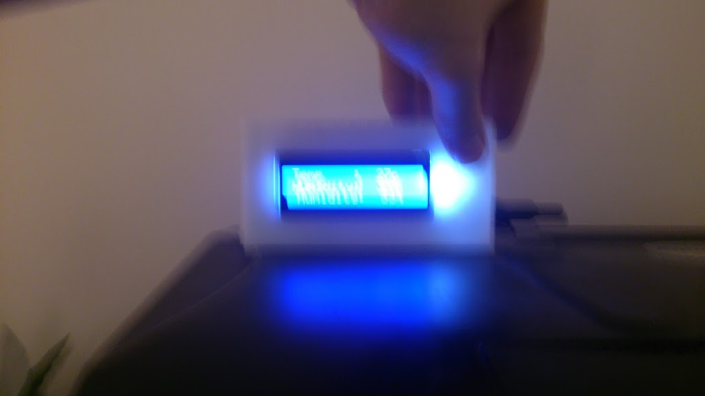
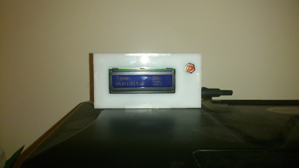
Gary the gecko gets a bit funny about his environment so we have to keep an eye on his temperature and humidity. We could have gone a purchased one but that would have been too easy! One ATMega328, home brewed PCB, LCD screen, DHT11 sensor and a laser cut case and we are away!
Not many notes on this one as the PCB creation was experimental and I will be writing it up fully later.
Anyway, here are some pictures.
More pics:

The button is so it doesn’t burn power with the backlight
Like this
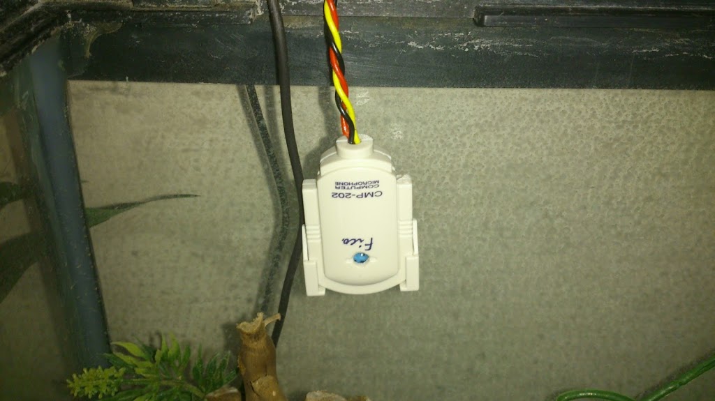
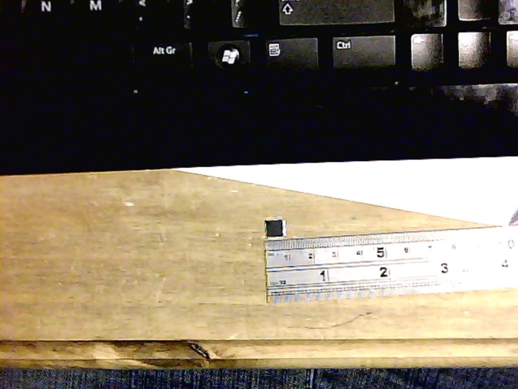
Sensor in an old mic housing.
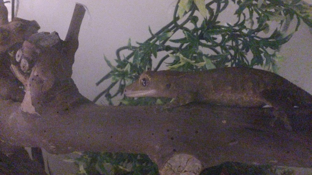
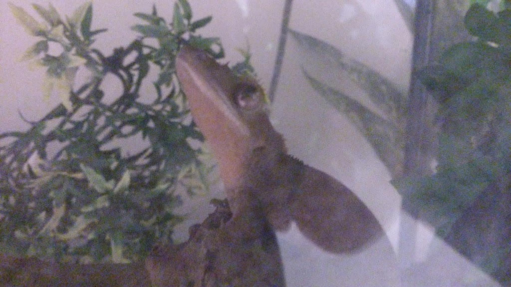
Gary
Gary
Code if you want it, un-tidied and barely changed from Adafruits code. You will want the library on the tutorial as well.
**************************************************
 // Example testing sketch for various DHT humidity/temperature sensors

// Written by ladyada, public domain

#include “DHT.h”
#define DHTPIN 13     // what pin we’re connected to
#include <LiquidCrystal.h>
LiquidCrystal lcd(5,6,7,8,9,10);
#define DHTTYPE DHT11   // DHT 11
// Connect pin 1 (on the left) of the sensor to +5V
// Connect pin 2 of the sensor to whatever your DHTPIN is
// Connect pin 4 (on the right) of the sensor to GROUND
// Connect a 10K resistor from pin 2 (data) to pin 1 (power) of the sensor

DHT dht(DHTPIN, DHTTYPE);

void setup() {
  lcd.begin(16, 2);
  lcd.clear();
  Serial.begin(9600);
  Serial.println(“DHTxx test!”);
  lcd.print(“Starting…”);
  dht.begin();
  delay(500);
}

void loop() {
  // Reading temperature or humidity takes about 250 milliseconds!
  // Sensor readings may also be up to 2 seconds ‘old’ (its a very slow sensor)
  int h = dht.readHumidity();
  int t = dht.readTemperature();

  // check if returns are valid, if they are NaN (not a number) then something went wrong!
  if (isnan(t) || isnan(h)) {
    Serial.println(“Failed to read from DHT”);
  }
  else {
    Serial.print(“Humidity: “);
    Serial.print(h);
    Serial.print(” %t”);
    Serial.print(“Temperature: “);
    Serial.print(t);
    Serial.println(” *C”);
  }

  //LCD Display
  lcd.clear();
  lcd.setCursor(0, 0);
  lcd.print(“Temp    : “);
  lcd.setCursor(11, 0);
  lcd.print(t);
  lcd.setCursor(13, 0);
  lcd.print(“c”);
  lcd.setCursor(0, 1);
  lcd.print(“Humidity: “);
  lcd.setCursor(11, 1);
  lcd.print(h);
  lcd.setCursor(13, 1);
  lcd.print(“%”);
  delay(1000);
}

*****************************************
Posted on

USB Microscope

We were lucky enough to be given a USB microscope this christmas so decided to try it out by soldering some Atmega8A in a TQFP32 package that we got REALLY cheap from China. We etched a breakout board using the vinyl on paper – laser print – heat transfer technique (we will write a post up about that later) and prepared to solder.

We realised they were small but hadn’t realised HOW small!


More after the break


Luckily we could get far closer than we will ever need to solder.


 The microscope can also record video – below is our first attempt at soldering this size package. So far everything seems to have been successful!


Not the most thrilling video in the world but it works!